
CFD computations and validations of the flow behind two ship stern alternatives
Hull form designers are constantly confronted with the problem of how to modify a given hull geometry to improve hydrodynamic performances. Fore body hull forms can be optimized relatively easily by minimizing wave resistance, but design of aft body hull forms has to be compromise between the conflicting requirements of acceptable wake flow quality and speed performance. The present leaflet shows one example of a SHIPFLOW application to an aft body design improvement by assessment of wake quality and resistance.
Case description
SSPA was contracted by Sungdong Shipbuilding and Marine Engineering Co. Ltd, in Korea to perform model tests for 170K B/C. Several candidate hull forms were developed by Sungdong in close cooperation with SSPA and SHIPFLOW computation were made for all design alternatives. Based on wake flow analysis, the best two designs were selected for final tank tests. This case is a typical design problem which designers are very often facing during the aft body hull lines design process. In the final investigation a more U shaped section (Version B), that would potentially give a better wake flow quality, was compared to a slightly more V shape section (Version A), that should give lower resistance. For proprietary reasons, only one section of the aft hulls is shown in the figure below. There are only minor differences between Version A and Version B. Hull B is created by taking hull A and adding slight modifications to make the velocity distribution at the propeller plane more uniform and thus improve the propulsion and cavitation characteristics.
The main objectives of this design study is to investigate:
- whether SHIPFLOW can predict the changes in the stern flow characteristics caused by small modification in the aft body lines.
- whether the direction of modification is right or not.
- whether the accuracy of the predictions is good enough for advanced design work
- whether the performance of the code will allow use of it as a design tool in a daily work .
Computations
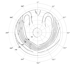
As the modification is confined in the aft body, only XCHAP computations are performed with medium (1,200,000 cells) and fine (2,400,000 cells) grids covering only the stern part of ship with double model option at model scale (Rn = 9.0x10⁶). The measured and computed wake at the propeller plane for the two aft body hull forms A and B are presented below.
Results
The difference in stern shape and the difference in measured wake contours are not large, however the code was able to predict the flow changes correctly. The predicted wake contours correspond very well to the measurements. The following small difference in the position of longitudinal center and wake contour shape can be noticed:
- The location of longitudinal center is shifted downward and inward in B's wake.
- The shape of the wake contours is more circular in B while more elliptical in A's wake.

A more detail comparison is given in the figures below, where a circumferential distribution of the total wake at four measured radii (r/R=0.45,0.64,0.82 and 1.0) is presented. In this graphs it can be seen that the wake distribution predicted with the CFD code follows exactly the measurements. Also the peak values and slope are correct which makes the code a very valuable tool for not only hull designers but also for the propeller experts.
Concluding Remarks
In recent years, SHIPFLOW has been more frequently used to give aids to various aft body design tasks and the present case for selecting the best one of two alternatives is one of many cases. SHIPFLOW can also provide detailed information of all local flow quantities which enable the designer to understand the physical reason why one design is better than the other and give him/her directions how to change a hull form to improve the design.