 Scale effects for optimization of a ship stern with CFD
Optimization of ship sterns
In the first part of this article we have described the optimization process of ship sterns using the SHIPFLOW CFD code. A brief reminder of the case is given below. Thereafter, a proposal for the next step in the modern hull design process is described.
The introduction of CFD methods made it possible to evaluate more hull variants and new generations of ships could be developed faster and with larger improvements. Introducing an automatic procedures the optimum hull is found given the prescribed objectives, constraints and design space. Knowledge and experience are required to define the geometry variations and constraints but the automatic optimization can greatly reduce the time spent on line modifications to do develop better hulls.
The first stern optimizations considered only the resistance in towed condition, while the propeller efficiency was estimated from wake quality measures.
In this article we show another approach for optimizing the ship performance by directly minimizing the delivered power.
Objective function for optimization
Using the Japanese Bulk Carrier (JBC) test case [1] it was shown in the first part of this article that the optimization of the aft body has to be done not in a towed but rather in a self-propelled condition.
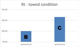
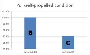
The first optimization is set up to minimize the resistance (towed condition). The second optimization minimizes the delivered power (Pd) in self-propelled condition at model scale. Hull C, optimized for Pd, was re-computed for the towed condition and the resistance was compared to hull B, optimized for resistance, Figure 1. The latter has a lower resistance as expected. Similarly hull B was also re-computed in self-propelled condition and Pd was compared to hull C, Figure 2. The comparison clearly shows that the increased propeller efficiency of hull C outbalances the higher resistance it has compared to hull B.
This exercise proves that the optimization of hulls should be performed in self-propelled condition to achieve the best results. The CFD tool gives us a possibility to get even closer to the optimum hull design with respect to the delivered power. The well known drawback of using towing tanks is that the scale effects have to be accounted for during post processing of the measurements. This is done based on empirical formulas and experience of towing tanks. Therefore, many assumptions are made which introduce uncertainty. The wake scaling based on these methods can hardly be considered as a universal approach to all hull shapes. This can be visible especially for ships equipped with energy saving devices (ESD) where no good recommendations exist.
Using SHIPFLOW the scale effect problem can be solved easily by computing the flow at the correct Reynolds number, hence obtaining the correct wake distribution witout mentioned approximations. In this part of the article we will look at a differences between optimization at model and at full scale.
Optimizations
In this part of the investigation CAESES from FRIENSHIP-SYSTEMS for the geometry variations and optimization and SHIPFLOW RANS 6.0 [2] for self-propulsion computations were used [3], [4], [5], [6].
The same partially parametric technique was chosen for the hull shape modifications the hull features and the design variable ranges remained unchanged as compared to the previous optimizations. Also the NSGA-II genetic algorithm parameters were the same to keep the approach consistent.
However, this time the optimization was run at the full scale Reynolds number.
Results
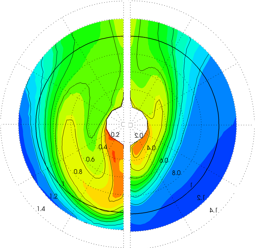
The scale effect between model Rn of 7.46e6 and full scale Rn of 2.10e9 is significant [8]. The boundary layer in which the propeller operates is much thinner at full scale, see Figure 3. The towing tank can provide measurements for the model scale while the full scale wake is only estimated. Since the difference is so large it is understandable that the hull optimization should be done at full scale Reynolds number directly.
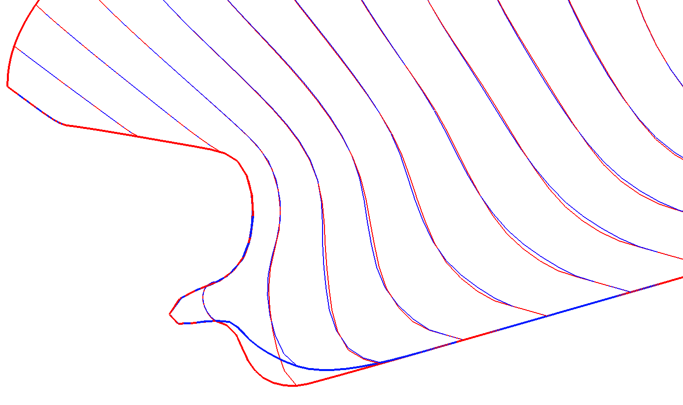
Unsurprisingly the optimizations at low and high Rn yielded a different hull shapes, see Figure 4, where the hull C in blue was optimized at model scale and hull D in red at full scale. The largest difference can be noticed in the profile of the boss but there are also differences in the sections shape further upstream.
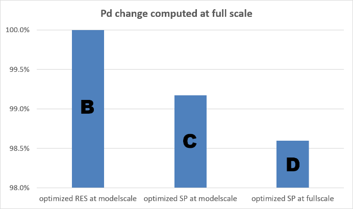
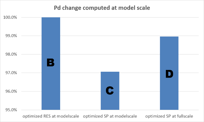
In the last step of this investigation all optimized hulls, i.e. B – optimized for best resistance at model scale, C – optimized for best delivered power at model scale and D – optimized for best delivered power at full scale, were compared both at model and full scale. As seen in the part 1 of this article hull C indicates lower Pd than hull B since it was optimized with running propeller. However, both were optimized at model scale and are worse as compared to hull D which was optimized directly at full scale, Figure 5. On the other hand when the computations are repeated at model scale hull D shows a higher Pd than hull C but still lower than hull B, Figure 6. This shows that it is not possible to optimize hulls properly in model scale.
Conclusions
The performed CFD based optimization at model and full scale clearly illustrates the necessity of optimizing of the sterns at the full scale. The wake in which the propeller operates changes drastically with increase of the Reynolds number. Therefore, it is understandable that the best results can be achieved when optimizing directly at full scale without involving scaling methods used in the design process applied in towing tanks.
Conclusions and recommendations:
- SHIPFLOW is capable of simulating full scale self propulsion
- Optimization at full scale using CFD is the future of ship design
- Partially parametric modelling delivered by CAESES gives very good control and flexibility of hull modifications, both global and local
- SHIPFLOW and CAESES is an excellent environment for hydrodynamic optimizations
Constraints for hard points and displacement as well as assessments of cavitation would normally be required in a commercial application. The same holds for hull surface roughness which can be important for real ships. However, this will not affect the conclusions made in this article.
Unlike model scale, there are only few validation data of low quality available from full scale. CFD methods can be verified and validated numerically for full scale, but better validation data at full scale is still required to increase the confidence to the level as for predictions based on towing tank procedures.
References
- NMRI. (2015). Tokyo 2015 A Workshop on CFD in Ship Hydrodynamics. Retrieved from http://www.t2015.nmri.go.jp/
- Broberg, L., Regnström, B., Östberg, M., (2007) ‘SHIPFLOW User Manual and Theoretical Manual’, FLOWTECH International AB, Gothenburg, Sweden
- Broberg, L., & Orych, M. (2012). An Efficient Numerical Technique to Simulate the Propeller Hull Interaction. International Journal of Innovative Research & Development, 14. PDF
- Han, K J (2008) “Numerical optimization of hull/propeller/rudder configurations”, PhD thesis, Department of Naval Architecture and Ocean Engineering, Division of Hydrodynamics, Chalmers University of Technology, Gothenburg, Sweden.
- Kim Keunjae and Li Daqing (2010): “Estimation of Numerical Uncertainty of SHIPFLOW in Self-propulsion Simulation of KCS”, G2010, Gothenburg 2010 Workshop on CFD in Ship Hydrodynamics
- Zhang D H (1990) Numerical computation of ship stern/propeller flow. Ph D thesis. Department of Naval Architecture and Ocean Engineering. Chalmers University of Technology
- Regnström, B., Broberg, L., & Larsson L. (2000) “Ship stern flow calculations on overlapping composite grids”, 23rd Symposium on Naval Hydrodynamics, Val de Reuil, France. PDF
- Larsson, L., Han, K. J., Bark, G., Regnstrom, B., and Bathfield N., “Numerical optimization of propeller-hull configuration at full scale”, World Maritime Technology Conference, March, 2006, London. PDF